HALL EFFECT MEASUREMENT SYSTEM

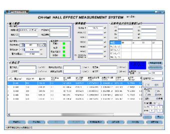
HALL EFFECT MEASUREMENT SYSTEM is used to measure the important parameters of Semiconductor Materials such as Carrier Concentration, Mobility, Resistivity, and Hall Coefficient, and so on. These parameters must be grasped and controlled in advance in order to understand the electrical characteristics of semiconductor materials. Therefore, the Hall Effect Measurement System is an indispensable tool for understanding and studying the electrical characteristics of Semiconductor Devices and Semiconductor Materials. The experimental results are automatically calculated by the software, and the Bulk Carrier Concentration, Sheet Carrier Concentration, Mobility, Resistivity, Hall Coefficient, Magneto-Resistance, and other parameters can be obtained at the same time.
HALL EFFECT MEASUREMENT SYSTEM

HALL EFFECT MEASUREMENT SYSTEM Attributes

HALL EFFECT MEASUREMENT SYSTEM

Item No.:

Product Name

and Model No.:

Main Technical Parameters

Product Images

1

Electromagnet

CH-50


1. Magnetic Field Strength (Magnetic Flux Density):

10 mm air gap between N and S, Max magnetic field: 1070 mT;

20 mm air gap between N and S, Max magnetic field: 678 mT;

30 mm air gap between N and S, Max magnetic field: 500 mT;

40 mm air gap between N and S, Max magnetic field: 378 mT;

50 mm air gap between N and S, Max magnetic field: 293 mT;


2. Magnetic Field Uniformity Volume: 10 mm

diameter at 10 mm air gap; Uniformity: 1 %;


3. Electromagnet Parameters:

3.1 Pole Core Diameter: φ 50 mm;

3.2 Pole Face Diameter: φ 50 mm;

3.3 Adjustable Pole Gap: 0 to 80 mm;

3.4 Coil Resistance: About 12.0 Ω;

3.5 Magnetic Field Stability: ± 0.3 Gs (within 24h);

3.6 Product Weight: 30 Kg.

2

Constant-Current Source

CH-2031


1. Output Voltage:

Nominal Output Voltage Range: 0 V to 60 V DC;

Open Circuit Output Voltage: 80 V ± 5 V @ 5 A;


2. Output Current: -5 A to +5 A DC;

(Current Linear Gradient Rate: 0.01 A / s to 2 A / s

 Continuously Adjustable, Max Sweeping Current Setting Range: 0.1 mA to 5 A DC);


3. High Stepping Resolution: 0.1 mA (1/50000 F.S.);


4. Accuracy: ± 0.2 % of set value + 5 mA);

Stability: Better than ± 0.1 % @ 5 A;


5. Noise / Ripple: 5 mA RMS Typical Value @ 5 A;


6. Communication Port: RS-232, which can be used for

 numerical control of polarity inversion, is convenient

 for the automated Hall Effect measurement process;


7. Interactive Capability:

White backlight FSTN LCD display screen;

LED Status Indicators;

The 3 x 4 Keys Interactive Function Keyboard

interacting with the screen and the indicator;

Standard RS-232C computer communication port

and Easy-to-Use connector features;

A complete set of computer interface command;

Timing and continuously triggering output function during sweeping;


8. Load Protection Function:

Instrument power fail protection;

instrument over-temperature protection;

instrument over-current protection;

instrument over-power protection.


3

Gaussmeter

CH-1300

1. Measuring Range: ± 1 Gs to ± 30 kGs;


2. Resolution: 1Gs;


3. Accuracy:

± 0.5 % of reading ± 0.05 % of measuring range;


4. Magnetic Measurement Sensor:

 Thickness: 1.0 mm;

Length: 100 mm;


5. Human-Computer Interaction:

Widescreen High-Resolution LCD Screen;

4¾ bit display;

Standard 9-pin "D" type RS232 connector;


6. Automation:

A complete set of computer interface command;

Through data communication, real-time monitoring and control of the magnetic field environment around the tested sample can be performed on the PC interface.


4

Sample Constant-Current Source

CH-320

1. Basic Current Output Resolution: 0.0001 uA;

  Basic Voltage Measurement Resolution: 0.0001 mV;


2. Output Measuring Range: 50.00 nA to 50.00 mA;

0.1 nA stepping can be continuously adjustable;


3. Measuring Voltage: 0 to ± 3 V; Large measuring-range test voltage could meet the high-resistance chip test;


4. Built-in Automatic Conversion Four-Phase Array

Card: can realize automatic measurement of Hall Effect Van Der Pauw method;


5. Good Human-Computer Interaction Interface: can be convenient for the user to make the manual adjustments;


6. A complete set of host computer command: can

communicate with PC to complete various

operations.

5

CH-35

Sample Stage

1. The sample stage can support the 30 * 30 mm size sample for testing;


2. The four-probe pressure point can make the operation of sample contact easier and firmer;


3. The external installation of light-proof components can ensure the test materials more stable;


4. The sample stage is fixed on the permanent magnet bracket, which can make the measured samples placed in the same position each time, ensuring to obtain the better repeatability of measurement;  


5. The signal connection, of which between the pins of sample stage and CH-320 Sample Constant-Current Source through the wire, can achieve the stable measurement of the Van Der Pauw method.

6

Host Computer Software


1. One-Key Automatic Measurement: after starting the

  test, the measurement can be carried out automatically without any manual operation;

2. The relevant parameters of the tested samples can be set in the software, and after the test being completed, each of parameters can be automatically calculated by the software;

3. I-V and B-V Curves can be carried out in the software;

4. The modular design in the software is convenient for the user to operate and develop the related

 functions;

5. After the tested results being completed, data will be temporarily saved in the software. If the long-term storage is required, the test data can be exported to the EXCEL file, which is convenient for the later data processing;

6. The data happened during the process of the test or in the final test can be saved for later data accessing;

7. The repeatedly circulating measurement can be carried out automatically;

8. Magneto-resistivity and Resistivity curves can be tested separately.

7

Auxiliary Devices


1. Fixing bracket for Gaussmeter sensor: All-aluminum and non-conductor bracket, which can be adjusted up and down, left and right, front and back, facilitates the users to adjust the sensor position according to their needs;


2. The related tools for making Ohmic Contact Solder Joints on the sample: Electric Soldering Iron, Indium Sheet, Solder, Enameled Wire, and so on;


3. The serial line for converting RS-232 to USB is used for the communication between the testing instrument and the host computer software;


4. Freely Available 1 Set of Hall Effect standard test

samples and data, which is provided from the Institute of Semiconductors, Chinese Academy of Sciences.


We take your privacy very seriously and when you visit our website, please agree to all cookies used.